Patrones de flujo en biorreactores: Rushton, pitched-blade y hydrofoil

Patrón de flujo en biorreactores: Rushton, Pitched-Blade e Hydrofoil

En un biorreactor agitado, el patrón de flujo está determinado por el diseño del impulsor. Algunas de las configuraciones más comunes son la turbina Rushton, el impulsor de palas inclinadas (pitched-blade) y el impulsor tipo hydrofoil.

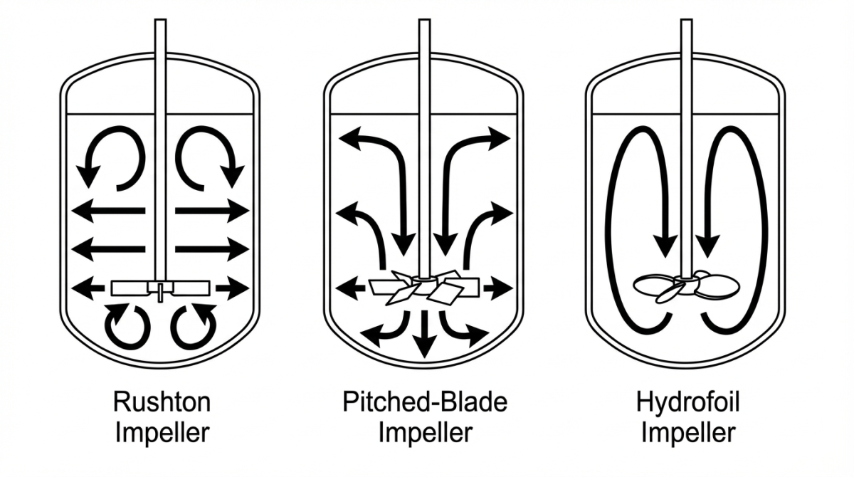
Cada uno genera un movimiento distinto: el impulsor Rushton impulsa el líquido lateralmente (flujo radial), las palas inclinadas combinan movimiento axial y radial, y el hydrofoil impulsa en dirección axial. Estas diferencias en la dirección del flujo influyen directamente en la mezcla, la dispersión de burbujas y la cizalla local.

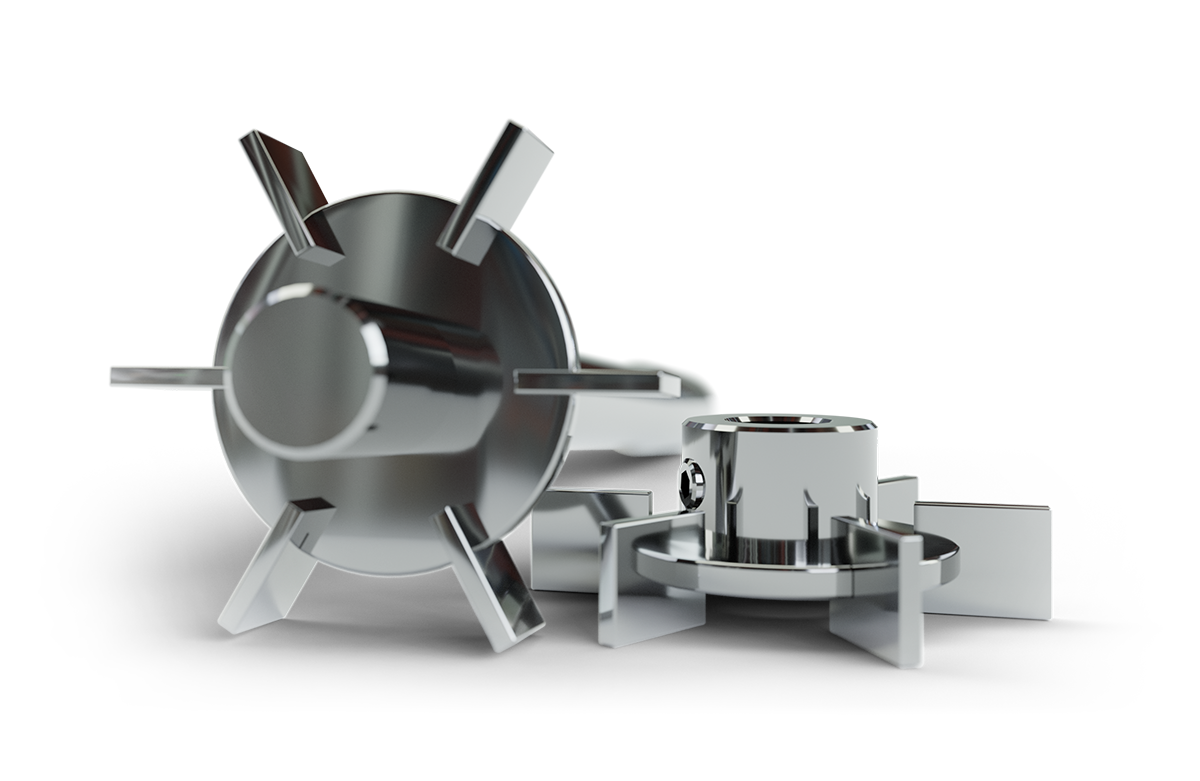
Impulsor Rushton: Flujo radial y alta cizalla

La turbina Rushton es un disco plano con 4–6 palas verticales. Su patrón de flujo es principalmente radial, lo que significa que el líquido se empuja hacia las paredes del tanque. Este chorro lateral genera aproximadamente la mitad del flujo hacia arriba y la otra mitad hacia abajo.

Como resultado, la turbina Rushton produce una intensa cizalla local, es decir, altas fuerzas cortantes cerca de cada pala. Además, sus palas planas son muy efectivas para romper burbujas de gas, lo que incrementa considerablemente la superficie de contacto entre el gas y el líquido. Todo esto se traduce en valores de kLa muy altos, lo que significa una excelente transferencia de oxígeno, aunque a costa de un mayor consumo de energía.

Los rasgos característicos del impulsor Rushton se resumen en:

  • Patrón de flujo radial: El flujo se distribuye hacia los costados del reactor.
  • Cizalla alta: Las palas planas generan fuertes turbulencias locales.
  • Transferencia de oxígeno (kLa) muy alta: Rompe eficazmente las burbujas de gas, alcanzando los kLa mayores.
  • Uso típico: Óptima en fermentaciones microbianas (p.ej. E. coli, levaduras) tolerantes a la cizalla. Se prefiere donde la prioridad es la oxigenación sobre la delicadeza celular.

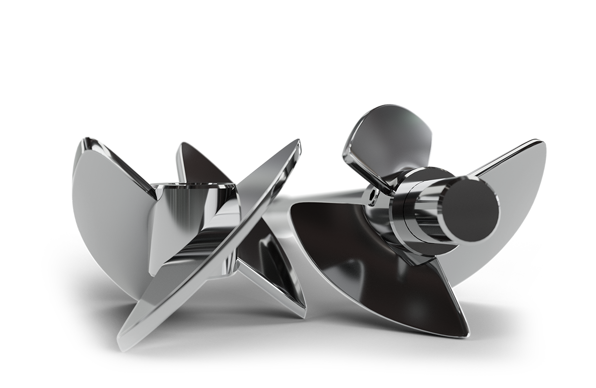
Impulsor pitched-blade: Flujo mixto axial-radial

El impulsor de palas inclinadas (pitched-blade) consta de 4–6 palas planas inclinadas unos 45° respecto al eje. Este diseño produce un flujo mixto axial-radial. Parte del fluido se mueve hacia arriba o hacia abajo (axial) y otra parte se desplaza hacia afuera (radial). El componente axial ayuda a elevar el fluido, mientras que el radial provoca cierta recirculación lateral. En la práctica, esto resulta en un flujo combinado que mezcla bien el medio, logrando un equilibrio entre el bombeo vertical y la turbulencia.

Los aspectos clave del pitched-blade son:

  • Patrón de flujo mixto: Combina flujo vertical y radial, reduciendo zonas muertas en el reactor.
  • Cizalla moderada: Menor que el impulsor Rushton, ya que el flujo axial amortigua el esfuerzo mecánico sobre las células.
  • Transferencia de oxígeno buena: Mantiene una dispersión de gas eficaz, aunque típicamente con kLa algo menor que Rushton a igual potencia.
  • Uso típico: Ideal para cultivos celulares sensibles (CHO, HEK, células de mamífero o insectos) que requieren buena mezcla sin un exceso de cizalla. También se emplea en procesos microbianos moderados y en mezclas líquido-líquido.

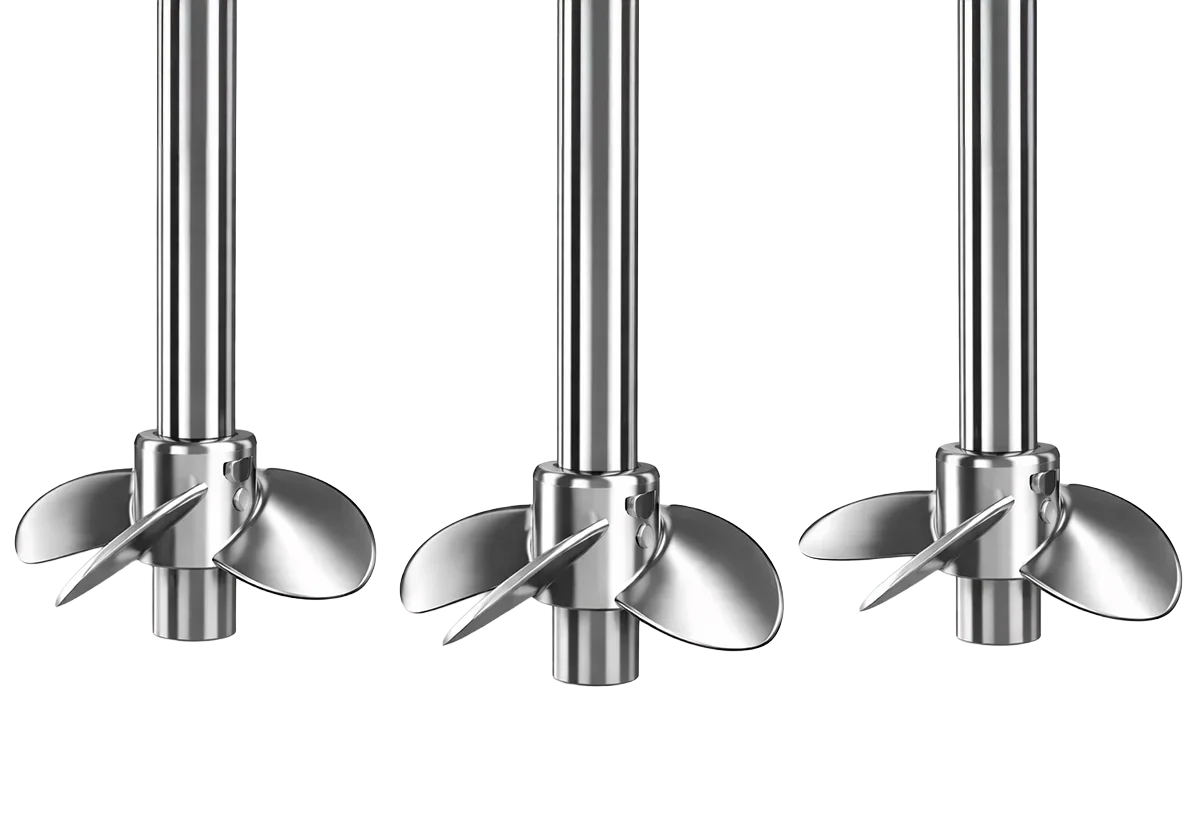
Impulsor hydrofoil: Flujo axial y mezcla de baja cizalla

El impulsor hydrofoil (o hélice hidrodinámica) tiene generalmente 3 a 4 palas curvas de perfil aerodinámico. El diseño de este sistema está pensado para crear un flujo principalmente axial, especialmente hacia abajo (down-pumping). Esto permite una recirculación vertical del líquido muy eficiente, utilizando muy poca energía. Gracias a la forma curva de las palas, el hydrofoil produce una cizalla mínima en comparación con otras geometrías. A bajas RPM, es capaz de mover grandes volúmenes de fluido, lo que ayuda a mantener la viabilidad de células delicadas.

Sus características clave son:

  • Flujo axial fuerte: Bombea el líquido verticalmente con eficiencia (flujo arriba/abajo).
  • Muy baja cizalla: Reduce las fuerzas cortantes, lo que es ideal para cultivos sensibles.
  • Alta eficiencia energética: Tiene un bajo número de potencia (Po), gran capacidad de bombeo y consumo mínimo de energia.
  • Transferencia de oxígeno: Aunque su kLa absoluto puede ser menor que el del impulsor Rushton, el alto caudal de recirculación mantiene una oxigenación efectiva.
  • Uso típico: Recomendado en cultivos muy delicados o medios viscosos (hasta decenas de miles de cP), en reactores de un solo uso y para escalado suave donde se minimiza el esfuerzo mecánico.

Comparación de patrones de flujo y rendimiento en biorreactores

Las diferencias se pueden resumir en la siguiente comparación. La dirección del flujo es distinta: la Rushton genera un flujo principalmente radial (hacia los lados), el pitched-blade produce un flujo mixto axial-radial, y el hydrofoil impulsa el líquido de manera axial (vertical). Además, la cizalla inducida es más alta con la Rushton, intermedia con el pitched-blade y baja con el hydrofoil.

En cuanto al rendimiento en la transferencia de oxígeno, también hay variaciones: la Rushton rompe las burbujas de manera muy eficiente (con un kLa muy alto), mientras que los impulsores axiales logran un kLa un poco más bajo a la misma potencia, pero mantienen una buena oxigenación gracias a una alta recirculación. Por último, el consumo energético es mayor en la Rushton (Po≈5–6), medio en el pitched-blade (Po≈2–3) y menor en el hydrofoil (Po≈1–1.2).

En resumen, los impulsores axiales (pitched-blade/hydrofoil) logran una mezcla más suave y eficiente por volumen impulsado, mientras que la Rushton proporciona la máxima dispersión de gas.

Cizalla, mezcla y transferencia de oxígeno en los patrones de flujo de biorreactores

En términos generales, los impulsores de flujo axial, como los de palas inclinadas y los hydrofoil, logran una mezcla más intensa que los radiales. Esto se traduce en mezclas homogéneas más rápidas con la misma potencia, además de reducir las áreas de cizalla extrema. Por otro lado, el impulsor Rushton genera turbulencias amplias que favorecen la dispersión de gas. Por ejemplo, todos los estudios coinciden en que los impulsores axiales superan a los radiales en cuanto a la intensidad de mezcla.

En lo que respecta al oxígeno disuelto, el Rushton ofrece los kLa más altos gracias a la ruptura violenta de burbujas, pero los impulsores axiales pueden compensar esto mediante una mejor circulación del fluido. En la práctica, con potencias similares, el Rushton suele tener la ventaja en kLa, mientras que el hydrofoil logra una buena oxigenación con un menor consumo energético al mantener un gran recirculado.

Suspensión celular y aplicaciones recomendadas

La elección del impulsor también depende del tipo de cultivo que estés manejando. Los organismos microbianos más robustos, como E. coli y las levaduras, son bastante resistentes a la alta cizalla, por lo que se suelen utilizar turbinas Rushton para maximizar la transferencia de oxígeno. Por otro lado, los cultivos más sensibles, como las células de mamífero o de insecto, requieren mezclas más suaves; en estos casos, los impulsores axiales son la mejor opción. Los impulsores de palas inclinadas y hydrofoil son excelentes para asegurar una buena circulación mientras mantienen baja la cizalla local.

Por ejemplo, las células CHO o HEK tienden a proliferar mejor con palas inclinadas o hydrofoil, ya que estos diseños ayudan a preservar la viabilidad celular al generar menos turbulencia. Para cultivos que son viscosos o de gran escala, el hydrofoil resulta ser especialmente útil: su diseño permite el manejo de fluidos de alta viscosidad (hasta aproximadamente 50,000 cP) y proporciona altos caudales con un esfuerzo mínimo. En contraste, los procesos mixtos o secuenciales pueden beneficiarse de la combinación de impulsores, como tener un impulsor de palas inclinadas arriba y un Rushton abajo, para equilibrar la mezcla y la oxigenación según sea necesario.

Tabla: comparación de los patrones de flujo de los impulsores más comunes en biorreactores

CaracterísticaRushton (turbina radial)Pitched-blade (PBT)Hydrofoil
Patrón de flujo (dominante)Radial (chorro horizontal intenso)Mixto axial–radial (descarga diagonal)Axial (bombeo vertical dominante)
Circulación típica en STR con baflesDos bucles toroidales (uno arriba y otro abajo del impulsor)Un bucle grande, depende de down- vs up-pumpingBucle vertical “limpio”, depende de down- vs up-pumping
Lo que mejor haceRotura de burbuja y dispersión de gasMezcla “todoterreno” del volumenGran recirculación con poca potencia
Cizalla cerca de las palasAltaModeradaBaja
Dispersión de gas / kLa (típico)Muy altaBuena (suele ser menor que Rushton a igual potencia)Buena respecto a la potencia (eficiente)
Eficiencia energética (tendencia Po)Baja (Po ~5–6)Media (Po ~2–3)Alta (Po ~1–1.2)
Casos de uso típicosFermentaciones microbianas aeróbicas (alta demanda de O₂)Cultivo celular y mezcla generalCultivos sensibles, escalado suave, medios viscosos

Cómo elegir el patrón de flujo adecuado para tu biorreactor

En un biorreactor STR, el patrón de flujo es una variable de proceso que condiciona la mezcla real del tanque, la dispersión de gas, el kLa alcanzable y, sobre todo, la exposición del cultivo a cizalla.

Si quieres profundizar en la selección del impulsor más allá del movimiento del fluido, te recomendamos el otro artículo de la serie, centrado en comparar Rushton, pitched-blade e hydrofoil desde el punto de vista de kLa, consumo energético, cizalla y criterios de escalado, para ayudarte a decidir con datos y no solo por “reglas rápidas”.

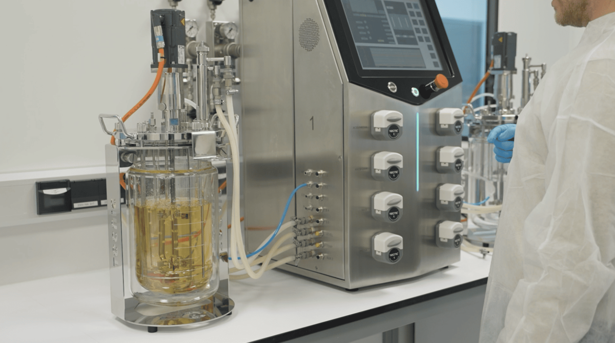
En este contexto, TECNIC ofrece biorreactores de un solo uso y de acero inoxidable multi-use configurables con turbinas Rushton y pitched-blade, lo que permite adaptar el sistema de agitación al tipo de proceso (microbiano o celular) y a la estrategia de escalado. Si necesitas validar qué patrón de flujo y configuración encajan mejor con tu cultivo, nuestro equipo puede asesorarte para definir la geometría y el sistema de agitación más adecuado para tu aplicación.

Bioreactor Flow Pattern FAQ

Frequently asked questions about flow patterns in stirred-tank bioreactors

1. What is a flow pattern in a stirred-tank bioreactor (STR)?

In an STR, the flow pattern is the dominant circulation path created by the impeller inside the vessel. It describes how liquid moves (axial, radial or mixed), which directly affects mixing time, gas dispersion, local shear and how quickly the whole tank becomes homogeneous.

2. What is the difference between axial, radial and mixed flow?

Radial flow pushes liquid sideways toward the tank wall (strong horizontal jet). Axial flow pumps liquid mainly up or down along the vessel axis (strong vertical circulation). Mixed flow combines both components, typically with a diagonal discharge that improves bulk circulation while maintaining some radial mixing.

3. What flow pattern does a Rushton turbine create?

A Rushton turbine is predominantly radial-flow. It generates a strong horizontal jet that hits the vessel wall and splits into two circulation loops (one above and one below the impeller), especially in baffled tanks. This pattern is typically associated with strong gas dispersion and high local turbulence.

4. What flow pattern does a pitched-blade (PBT) impeller create?

A pitched-blade turbine produces mixed axial–radial flow. The discharge leaves the blades diagonally, so the impeller can pump up or down (depending on blade orientation), while still generating a radial component that helps distribute flow across the vessel diameter.

5. What flow pattern does a hydrofoil impeller create?

Hydrofoil impellers are mainly axial-flow designs. They are optimised to move large liquid volumes vertically (strong pumping) with relatively low power input, typically creating a clean vertical circulation loop that supports efficient bulk mixing at lower local shear.

6. How do baffles affect the flow pattern in a stirred-tank bioreactor?

Baffles (typically 3–4 vertical plates) reduce swirl and suppress vortex formation, so more of the impeller power is converted into a defined flow pattern (axial, radial or mixed) instead of “spinning” the whole liquid volume. In baffled STRs, circulation loops become more stable, mixing time usually improves, and gas dispersion tends to be more consistent. Without baffles, strong tangential motion can dominate, leading to poor top-to-bottom exchange, surface vortexing and less predictable oxygen transfer.

7. Does down-pumping vs up-pumping matter for pitched-blade and hydrofoil impellers?

Yes. Blade orientation determines whether the impeller pumps liquid downward or upward, which changes where high-velocity zones form and how quickly the top and bottom of the tank exchange fluid. Down-pumping is often preferred for surface-to-bottom circulation and gas handling, while up-pumping can be useful in specific suspension or surface renewal scenarios.

8. How does flow pattern influence mixing time and dead zones?

Axial and mixed-flow impellers typically improve top-to-bottom circulation and reduce stagnant regions, especially in taller tanks. Radial turbines can mix efficiently near the impeller zone but may require multiple impellers or specific placement to avoid stratification in large volumes.

9. How does flow pattern relate to gas dispersion and kLa?

Gas dispersion depends on how the impeller interacts with bubbles and where gas is carried in the vessel. Radial turbines often break bubbles efficiently and can deliver high kLa at higher power. Axial designs can maintain effective oxygenation by sustaining strong circulation and distributing bubbles throughout the working volume, depending on sparger and gas rate.

10. When should I use multiple impellers to control the flow pattern?

Multiple impellers are common in tall vessels, higher viscosity media or large-scale STRs where one impeller cannot circulate the entire height effectively. Adding a second (or third) impeller helps stabilise axial circulation, reduce stratification and improve overall gas and nutrient distribution across the full liquid column.

Referencias

Este artículo presenta un análisis técnico y basado en datos de los impulsores para biorreactores, comparando los diseños Rushton, pitched-blade e hydrofoil desde la perspectiva de los patrones de flujo, la transferencia de oxígeno (kLa), el entorno de cizalla y la eficiencia energética en biorreactores agitados de escala laboratorio, piloto y producción. El contenido está estructurado para ayudar a entender cómo el flujo generado por el impulsor influye en el comportamiento de la mezcla y cómo estas diferencias afectan al rendimiento del proceso y a las decisiones de escalado.

Este artículo ha sido revisado y publicado por TECNIC Bioprocess Solutions, fabricante de biorreactores agitados escalables, sistemas de filtración de flujo tangencial y consumibles de un solo uso para el desarrollo de bioprocesos, operaciones piloto y fabricación bajo GMP.

Subscribe to our newsletter

Newsletter Form

Contact form

Your opinion is very important to us, and we encourage you to contact our sales team to discuss the purchase of our bioprocess equipment. We are here to answer your questions and help you find the best solution for your needs.

Quote
Related Content

Quote

Quote
Image to access to all TECNIC's features, you can see a person working with the ePilot Bioreactor.

Coming soon 

We are finalizing the details of our new equipment. Soon, we will announce all the updates. If you want to receive all the latest news about our products, subscribe to our newsletter or follow our social media channels. 

Newsletter Form

Sign Up

Stay informed about our product innovations, best practices, exciting events and much more! After signing up for our newsletter, you can unsubscribe at any time.

Newsletter Form

Cassette

We understand the importance of flexibility and efficiency in laboratory processes. That's why our equipment is designed to be compatible with Cassette filters, an advanced solution for a variety of filtration applications. Although we do not manufacture the filters directly, our systems are optimized to take full advantage of the benefits that Cassette filters offer.

Cassette filters are known for their high filtration capacity and efficiency in separation, making them ideal for ultrafiltration, microfiltration, and nanofiltration applications. By integrating these filters into our equipment, we facilitate faster and more effective processes, ensuring high-quality results.

Our equipment, being compatible with Cassette filters, offers greater versatility and adaptability. This means you can choose the filter that best suits your specific needs, ensuring that each experiment or production process is carried out with maximum efficiency and precision.

Moreover, our equipment stands out for its 100% automation capabilities. Utilizing advanced proportional valves, we ensure precise control over differential pressure, transmembrane pressure, and flow rate. This automation not only enhances the efficiency and accuracy of the filtration process but also significantly reduces manual intervention, making our systems highly reliable and user-friendly.

Hollow Fiber

We recognize the crucial role of flexibility and efficiency in laboratory processes. That's why our equipment is meticulously designed to be compatible with Hollow Fiber filters, providing an advanced solution for a broad spectrum of filtration applications. While we don't directly manufacture these filters, our systems are finely tuned to harness the full potential of Hollow Fiber filters.

Hollow Fiber filters are renowned for their exceptional performance in terms of filtration efficiency and capacity. They are particularly effective for applications requiring gentle handling of samples, such as in cell culture and sensitive biomolecular processes. By integrating these filters with our equipment, we enable more efficient, faster, and higher-quality filtration processes.

What sets our equipment apart is its 100% automation capability. Through the use of sophisticated proportional valves, our systems achieve meticulous control over differential pressure, transmembrane pressure, and flow rate. This level of automation not only boosts the efficiency and precision of the filtration process but also significantly diminishes the need for manual oversight, rendering our systems exceptionally reliable and user-friendly.

Contact General

Cellular configuration

The cellular configuration of the eLab Advanced is equipped with a pitched-blade impeller designed to support efficient mixing for cell culture processes in both laboratory development and early scale-up. The blade geometry promotes mainly axial flow, helping to distribute gases, nutrients and pH control agents uniformly throughout the vessel while keeping shear stress at a moderate level. This makes it suitable for mammalian, insect and other shear-sensitive cell lines when operated with appropriate agitation and aeration settings. In combination with the vessel aspect ratio and baffle design, the pitched blade supports stable foaming behavior and reproducible oxygen transfer, which is essential when comparing batches or transferring processes between working volumes.

Operators can fine-tune agitation speed to balance oxygen demand and mixing time without excessively increasing mechanical stress on the culture. 

Microbial configuration

The microbial configuration of the eLab Advanced is equipped with a Rushton turbine specifically designed for high-oxygen-demand processes such as bacterial and yeast fermentations. The radial-flow impeller generates strong mixing and intense gas dispersion, promoting high oxygen transfer rates and fast homogenization of nutrients, antifoam and pH control agents throughout the vessel. This makes it particularly suitable for robust microbial strains operating at elevated agitation speeds and aeration rates.

Operators can adjust agitation and gas flow to reach the required kLa while maintaining consistent mixing times, even at high cell densities. This configuration is an excellent option for users who need a powerful, reliable platform to develop and optimize microbial processes before transferring them to pilot or production scales.

Cellular configuration

The cellular configuration of the eLab Advanced is equipped with a pitched-blade impeller designed to support efficient mixing for cell culture processes in both laboratory development and early scale-up. The blade geometry promotes mainly axial flow, helping to distribute gases, nutrients and pH control agents uniformly throughout the vessel while keeping shear stress at a moderate level. This makes it suitable for mammalian, insect and other shear-sensitive cell lines when operated with appropriate agitation and aeration settings. In combination with the vessel aspect ratio and baffle design, the pitched blade supports stable foaming behavior and reproducible oxygen transfer, which is essential when comparing batches or transferring processes between working volumes.

Operators can fine-tune agitation speed to balance oxygen demand and mixing time without excessively increasing mechanical stress on the culture. 

Technical specifications

Materials and finishes

Typical
  • Product-contact parts: AISI 316L (1.4404), typical Ra < 0.4 µm (16 µin)
  • Non-contact parts/skid: AISI 304/304L
  • Seals/elastomers: platinum-cured silicone, EPDM and/or PTFE (material set depends on selection)
  • Elastomers compliance (depending on selected materials): FDA 21 CFR 177.2600 and USP Class VI
  • Surface treatments: degreasing, pickling and passivation (ASTM A380 and ASTM A968)
  • Roughness control on product-contact surfaces

Design conditions

Pressure & temperature

Defined considering non-hazardous process fluids (PED group 2) and jacket steam/superheated water (PED group 5), depending on configuration and project scope.

Reference design envelope
ModeElementWorking pressure (bar[g])Working pressure (psi[g])T max (°C / °F)
ProcessVessel0 / +2.50 / +36.3+90 / 194
ProcessJacket0 / +3.80 / +55.1+90 / 194
SterilisationVessel0 / +2.50 / +36.3+130 / 266
SterilisationJacket0 / +3.80 / +55.1+150 / 302
Jacket working pressure may also be specified as 0 / +4 bar(g) (0 / +58.0 psi[g]) depending on design selection; final values are confirmed per project.

Pressure control and safeguards

Typical
  • Designed to maintain a vessel pressure set-point typically in the range 0 to 2.5 bar(g)
  • Aseptic operation commonly around 0.2 to 0.5 bar(g) to keep the vessel slightly pressurised
  • Overpressure/underpressure safeguards included per configuration and regulations
  • Pressure safety device (e.g., rupture disc and/or safety valve) included according to configuration

Agitation

Reference ranges
Working volumeMU (Cell culture), referenceMB (Microbial), reference
10 L0 to 300 rpm0 to 1000 rpm
20 L0 to 250 rpm0 to 1000 rpm
30 L0 to 200 rpm0 to 1000 rpm
50 L0 to 180 rpm0 to 1000 rpm

Integrated peristaltic pumps (additions)

Typical

The equipment typically includes 4 integrated variable-speed peristaltic pumps for sterile additions (acid/base/antifoam/feeds). Actual flow depends on selected tubing and calibration.

ParameterTypical valueNotes
Quantity4 units (integrated)In control tower; assignment defined by configuration
Speed0-300 rpmVariable control from eSCADA
Minimum flow0-10 mL/minExample with 0.8 mm ID tubing; depends on tubing and calibration
Maximum flowUp to ~366 mL/minExample with 4.8 mm ID tubing; actual flow depends on calibration
Operating modesOFF / AUTO / MANUAL / PROFILEAUTO typically associated to pH/DO/foam loops or recipe
FunctionsPURGE, calibration, totaliser, PWMPWM available for low flow setpoints below minimum operating level

Gas flow control (microbial reference capacity)

Reference

For microbial culture (MB), gas flow controllers (MFC) are typically sized based on VVM targets. Typical reference VVM range: 0.5-1.5 (to be confirmed by process).

Working volume (L)VVM minVVM maxAir (L/min)O2 (10%) (L/min)CO2 (20%) (L/min)N2 (10%) (L/min)
100.51.55-150.5-1.51-30.5-1.5
200.51.510-301-32-61-3
300.51.515-451.5-4.53-91.5-4.5
500.51.525-752.5-7.55-152.5-7.5
O2/CO2/N2 values are shown as reference capacities for typical gas blending strategies (10% O2, 20% CO2, 10% N2). Final gas list and ranges depend on process and configuration.

Instrumentation and sensors

Typical

Instrumentation is configurable. The following list describes typical sensors integrated in standard configurations, plus common optional PAT sensors.

Variable / functionTypical technology / interfaceStatus (STD/OPT)
Temperature (process/jacket)Pt100 class A RTDSTD
Pressure (vessel/lines)Pressure transmitter (4-20 mA / digital)STD
Level (working volume)Adjustable probeSTD
pHDigital pH sensor (ARC or equivalent)STD
DO (pO2)Digital optical DO sensor (ARC or equivalent)STD
FoamConductive/capacitive foam sensorSTD
Weight / mass balanceLoad cell (integrated in skid)STD
pCO2Digital pCO2 sensor (ARC or equivalent)OPT
Biomass (permittivity)In-line or in-vessel sensorOPT
VCD / TCDIn-situ cell density sensorsOPT (MU)
Off-gas (O2/CO2)Gas analyser for OUR/CEROPT
ORP / RedoxDigital ORPOPT
Glucose / LactatePAT sensorOPT

Automation, software and connectivity

Typical

The platform incorporates TECNIC eSCADA (typically eSCADA Advanced for ePILOT) to operate actuators and control loops, execute recipes and manage process data.

Main software functions
  • Main overview screen with process parameters and trends
  • Alarm management (real-time alarms and historical log) with acknowledgement and comment option
  • Manual/automatic modes for actuators and control loops
  • Recipe management with phases and transitions; parameter profiles (multi-step) for pumps and setpoints
  • Data logging with configurable period and export to CSV; PDF report generation
Common control loops
  • Temperature control (jacket heating/cooling)
  • Pressure control (headspace) with associated valve management
  • pH control via acid/base addition pumps and optional CO2 strategy
  • DO control with cascade strategies (agitation, air, O2, N2) depending on package and configuration
  • Foam control (foam sensor and automatic antifoam addition)
Data integrity and 21 CFR Part 11

Support for 21 CFR Part 11 / EU GMP Annex 11 is configuration- and project-dependent and requires customer procedures and validation (CSV).

Utilities

Reference

Utilities depend on final configuration (e.g., AutoSIP vs External SIP) and destination market (EU vs North America). The following values are typical reference points.

UtilityTypical service / configurationPressureFlow / powerNotes
ElectricalEU base: 400 VAC / 50 Hz (3~)N/AAutoSIP: 12 kW; External SIP: 5 kWNA option: 480 VAC / 60 Hz; cabinet/wiring per NEC/NFPA 70; UL/CSA as required
Process gasesAir / O2 / CO2 / N2Up to 2.5 bar(g) (36.3 psi)According to setpointTypical OD10 pneumatic connections; final list depends on package
Instrument airPneumatic valvesUp to 6 bar(g) (87.0 psi)N/ADry/filtered air recommended
Cooling waterJacket cooling water2 bar(g) (29.0 psi)25 L/min (6.6 gpm)6-10 °C (43-50 °F) typical
Cooling waterCondenser cooling water2 bar(g) (29.0 psi)1 L/min (0.26 gpm)6-10 °C (43-50 °F) typical
Steam (External SIP)Industrial steam2-3 bar(g) (29.0-43.5 psi)30 kg/h (66 lb/h)For SIP sequences
Steam (External SIP)Clean steam1.5 bar(g) (21.8 psi)8 kg/h (18 lb/h)Depending on plant strategy

Compliance and deliverables

Typical

Depending on destination and project scope, the regulatory basis may include European Directives (CE) and/or North American codes. The exact list is confirmed per project and stated in the Declaration(s) of Conformity when applicable.

ScopeEU (typical references)North America (typical references)
Pressure equipmentPED 2014/68/EUASME BPVC Section VIII (where applicable)
Hygienic designHygienic design good practicesASME BPE (reference for bioprocessing)
Machine safetyMachinery: 2006/42/EC (until 13/01/2027) / (EU) 2023/1230OSHA expectations; NFPA 79 (industrial machinery) - project dependent
Electrical / EMCLVD 2014/35/EU; EMC 2014/30/EUNEC/NFPA 70; UL/CSA components and marking as required
Materials contactEC 1935/2004 + EC 2023/2006 (GMP for materials) where applicableFDA 21 CFR (e.g., 177.2600 for elastomers) - materials compliance
Software / CSVEU GMP Annex 11 (if applicable)21 CFR Part 11 (if applicable)
Standard documentation package
  • User manual and basic operating instructions
  • P&ID / layout drawings as per project scope
  • Material certificates and finish/treatment certificates (scope dependent)
  • FAT report (if included in contract)
Optional qualification and commissioning services
  • SAT (Site Acceptance Test)
  • IQ / OQ documentation and/or execution (scope agreed with customer)
  • CSV support package for regulated environments (ALCOA+ considerations, backups, time synchronisation, etc.)

Ordering and configuration

Project-based

ePILOT BR is configured per project. To define the right MU/MB package, volumes and options (utilities, sensors, software and compliance), please contact TECNIC with your URS or request the configuration questionnaire.

The information provided above is for general reference only and may be modified, updated or discontinued at any time without prior notice. Values and specifications are indicative and may vary depending on project scope, configuration and applicable requirements. This content does not constitute a binding offer, warranty, or contractual commitment. Any final specifications, deliverables and acceptance criteria will be confirmed in the corresponding quotation, technical documentation and/or contract documents.

Cellular configuration

The cellular configuration of the eLab Advanced is equipped with a pitched-blade impeller designed to support efficient mixing for cell culture processes in both laboratory development and early scale-up. The blade geometry promotes mainly axial flow, helping to distribute gases, nutrients and pH control agents uniformly throughout the vessel while keeping shear stress at a moderate level. This makes it suitable for mammalian, insect and other shear-sensitive cell lines when operated with appropriate agitation and aeration settings. In combination with the vessel aspect ratio and baffle design, the pitched blade supports stable foaming behavior and reproducible oxygen transfer, which is essential when comparing batches or transferring processes between working volumes.

Operators can fine-tune agitation speed to balance oxygen demand and mixing time without excessively increasing mechanical stress on the culture. 

Technical specifications

[contact-form-7 id="c5c798c" title="ePilot BR configuration questionnaire"]

Cellular configuration

The cellular configuration of the eLab Advanced is equipped with a pitched-blade impeller designed to support efficient mixing for cell culture processes in both laboratory development and early scale-up. The blade geometry promotes mainly axial flow, helping to distribute gases, nutrients and pH control agents uniformly throughout the vessel while keeping shear stress at a moderate level. This makes it suitable for mammalian, insect and other shear-sensitive cell lines when operated with appropriate agitation and aeration settings. In combination with the vessel aspect ratio and baffle design, the pitched blade supports stable foaming behavior and reproducible oxygen transfer, which is essential when comparing batches or transferring processes between working volumes.

Operators can fine-tune agitation speed to balance oxygen demand and mixing time without excessively increasing mechanical stress on the culture. 

Technical specifications

Models and working volumes

Tank

The ePlus Mixer platform combines an ePlus Mixer control tower with Tank frames and eBag 3D consumables. Tank can be supplied in square or cylindrical configurations (depending on project) to match the bag format.

Tank modelNominal volumeMinimum volume to start agitation*
Tank 50 L50 L15 L
Tank 100 L100 L20 L
Tank 200 L200 L30 L
Tank 500 L500 L55 L
*Values based on agitation start interlocks per tank model. Final performance depends on the selected eBag 3D, fluid properties and configuration.

Design conditions and operating limits

Reference

Reference limits are defined for the ePlus Mixer and the Tank. It is recommended to validate the specific limits of the selected eBag 3D and single-use sensors for the customer’s process.

ElementOperating pressureMaximum pressure (safety)Maximum working temperature
ePlus Mixer (control tower)ATM0.5 bar(g)90 °C
TankATM0.5 bar(g)45 °C
Jacket (if applicable)N/A1.5 barDepends on utilities / scope
The 0.5 bar(g) limit is associated with the equipment design, the circuit is protected by a safety valve. Confirm final limits on the equipment nameplate and project specification.

Materials and finishes

Typical
  • Control tower housing and frame: stainless steel 304
  • Product-contact metallic hard parts (if applicable): stainless steel 316 (defined in project manufacturing documentation)
  • Non-product-contact metallic parts: stainless steel 304
  • eBag consumable: single-use polymer (supplier dependent, gamma irradiation / sterilisation per specification)
  • Vent filters: PP (polypropylene), per component list
For GMP projects, the recommended documentation package includes material certificates, surface finish certificates (Ra if applicable) and consumable sterility/irradiation certificates.

Agitation system

Magnetic

Non-invasive magnetic agitation, the impeller is integrated in the eBag 3D Mixer format, avoiding mechanical seals. Agitation speed is controlled from the HMI, with start interlocks linked to the tank model and minimum volume.

Reference speed range
  • Typical agitation range: 120 to 300 rpm (configuration dependent)
  • Magnetic drive motor (reference): Sterimixer SMA 85/140, 50 Hz, 230/400 V, 0.18 kW
  • Gear reduction (reference): 1:5
  • Actuation (reference): linear actuator LEYG25MA, stroke 30–300 mm, speed 18–500 mm/s (for positioning)
Final rpm and mixing performance depend on tank size, bag format and process requirements.

Weighing and volume control

Integrated

Weight and derived volume control are performed using 4 load cells integrated in the tank frame legs and a weight indicator. Tare functions are managed from the HMI to support preparation steps and additions by mass.

ComponentReference modelKey parameters
Load cells (x4)Mettler Toledo SWB505 (stainless steel)550 kg each, output 2 mV/V, IP66
Weight indicatorMettler Toledo IND360 DINAcquisition and HMI display, tare and “clear last tare”
For installation engineering, total floor load should consider product mass + equipment mass + margin (recommended ≥ 20%).

Pumps and fluid handling

Standard

The platform includes integrated pumps for additions and circulation. Final tubing selection and calibration define the usable flow range.

Included pumps (reference)
  • 3 integrated peristaltic pumps for additions (acid/base/media), with speed control from HMI
  • 1 integrated centrifugal pump for circulation / transfer (DN25)
Peristaltic pumps (reference)
ParameterReferenceNotes
Quantity3 unitsIntegrated in the control tower
Pump headHYB101 (Hygiaflex)Example tubing: ID 4.8 mm, wall 1.6 mm
Max speed300 rpmSpeed control reference: 0–5 V
Max flow (example)365.69 mL/minDepends on tubing and calibration
Centrifugal pump (reference)
ParameterReference
ModelEBARA MR S DN25
Power0.75 kW
FlowUp to 42 L/min
PressureUp to 1 bar
For circulation and sensor loops, the eBag 3D format can include dedicated ports (depending on the selected consumable and application).

Thermal management (optional jacket)

Optional

Tank can be supplied with a jacket (single or double jacket options). The thermal circuit includes control elements and a heat exchanger, enabling temperature conditioning depending on utilities and project scope.

  • Jacket maximum pressure (reference): 1.5 bar
  • Thermal circuit safety: pressure regulator and safety valve (reference set-point 0.5 bar(g))
  • Heat exchanger (reference): T5-BFG, 12 plates, alloy 316, 0.5 mm, NBRP
  • Solenoid valves (reference): SMC VXZ262LGK, 1", DC 24 V, 10.5 W
  • Jacket sequences: fill / empty / flush (scope dependent)
The tank maximum temperature may depend on the thermal circuit and consumable limits. Confirm final values with the selected eBag 3D specification.

Instrumentation and sensors

Optional SU

Single-use sensors can be integrated via dedicated modules. The following references describe typical sensors and interfaces listed in the datasheet.

VariableReference modelInterface / protocolSupplyOperating temperatureIP
pHOneFerm Arc pH VP 70 NTC (SU)Arc Module SU pH, Modbus RTU7–30 VDC5–50 °CIP67
ConductivityConducell-P SU (SU)Arc Module Cond-P SU, Modbus RTU7–30 VDC0–60 °CIP64
TemperaturePt100 ø4 × 52 mm, M8 (non-invasive)Analog / acquisition moduleProject dependentProject dependentProject dependent
Measurement ranges and final sensor list depend on the selected single-use components and project scope.

Automation, software and data

Standard + options

The ePlus SUM control tower integrates an industrial PLC and touch HMI. Standard operation supports Manual / Automatic / Profile modes, with optional recipe execution depending on selected software scope.

Software scope (reference)
  • Standard: eBASIC (base HMI functions)
  • Optional: eSCADA Basic or eSCADA Advanced (project dependent)
  • Trends, alarms and profiles, profiles up to 100 steps (depending on scope)
  • Data retention (reference): up to 1 year
Connectivity (reference)
  • Industrial Ethernet and integrated OPC server (included)
  • Remote access option (project dependent)

Utilities and facility interfaces

Typical

Installation requirements depend on jacket and temperature scope and the customer layout. The following values are typical references.

UtilityPressureFlowConnectionsNotes
Electrical supplyN/AReference: 18 A380–400 VAC, 3~ + N, 50 HzConfirm per final configuration and destination market
EthernetN/AN/ARJ45OPC server, LAN integration
Tap water2.5 barN/A1/2" (hose connection)Jacket fill and services, tank volume about 25 L
Cooling water2–4 bar10–20 L/min2 × 3/4" (hose connection)Heat exchanger and jacket cooling
Process air2–4 barN/A1/2" quick couplingUsed for jacket emptying
DrainN/AN/A2 × 3/4" (hose connection)For draining
ExhaustN/AN/AN/AOptional (depending on project)
Stack light (optional)N/AN/AN/A3-colour indication, as per scope
During FAT, verify in the installation checklist that the available utilities match the selected configuration and scope.

Documentation and deliverables

Project-based

Deliverables depend on scope and project requirements. The following items are typical references included in the technical documentation package.

  • Datasheet and user manual (HMI and system operation)
  • Electrical schematics, PLC program and backup package (scope dependent)
  • P&ID, layout and GA drawings (PDF and/or CAD formats, project dependent)
  • Factory Acceptance Test (FAT) protocol and FAT report (as per contract)
  • Installation checklist
  • Material and consumable certificates, as required for regulated projects (scope dependent)
On-site services (SAT, IQ/OQ) and extended compliance packages are optional and defined per project.

Ordering and configuration

Contact

The ePlus Mixer scope is defined per project. To select the right tank size, bag format, sensors and optional jacket and software, please share your URS or request the configuration questionnaire.

The information provided above is for general reference only and may be modified, updated or discontinued at any time without prior notice. Values and specifications are indicative and may vary depending on project scope, configuration and applicable requirements. This content does not constitute a binding offer, warranty, or contractual commitment. Any final specifications, deliverables and acceptance criteria will be confirmed in the corresponding quotation, technical documentation and/or contract documents.

Cellular configuration

The cellular configuration of the eLab Advanced is equipped with a pitched-blade impeller designed to support efficient mixing for cell culture processes in both laboratory development and early scale-up. The blade geometry promotes mainly axial flow, helping to distribute gases, nutrients and pH control agents uniformly throughout the vessel while keeping shear stress at a moderate level. This makes it suitable for mammalian, insect and other shear-sensitive cell lines when operated with appropriate agitation and aeration settings. In combination with the vessel aspect ratio and baffle design, the pitched blade supports stable foaming behavior and reproducible oxygen transfer, which is essential when comparing batches or transferring processes between working volumes.

Operators can fine-tune agitation speed to balance oxygen demand and mixing time without excessively increasing mechanical stress on the culture. 

Scale

Bioreactors engineered for smooth scale-up

From S to XL, with a clear scale path

Move from laboratory to pilot and production with a structured range: eLab (0.5–10 L), ePilot (30–50 L), eProd (100–2000 L). Scale with clearer continuity across platforms, supporting the same key control priorities and configuration paths for a smoother transition between volumes.